In this issue:
Guided Bone Regeneration: 8 Steps to Successful Ridge Augmentation (1 CEU)
Author
The ideal placement of dental implants is often compromised because of existing alveolar ridge deficiencies. The lack of available bone for proper implant placement may be caused by many factors, including developmental anomalies, trauma and, most commonly, tooth extraction. It is widely accepted and documented in the literature that after a tooth is extracted, resorption of the alveolar bone occurs in both a horizontal and vertical dimension, which results in a compromised volume of bone.
To reestablish the ideal bony contours and restore bony defects, effective bone augmentation techniques have been developed. The concept of guided bone regeneration (GBR) was introduced to the profession over 30 years ago and entails using a barrier membrane during the healing process to exclude certain nonideal cell types, thereby allowing the growth of slower-growing bone cells.1 Basically, osteoprogenitor cells, which differentiate into osteoblast bone-forming cells, are able to repopulate the graft site because of the mechanics of the exclusion membrane.2 Studies have shown that up to 40% of dental implant sites require GBR procedures as part of the patient’s rehabilitation.3
For success and predictability, clinicians must adhere to the factors and principles that are paramount to regenerating bony contours for implant placement. If implant placement is attempted in a deficient bony ridge, the function, support and esthetics may be compromised. A successful bone graft relies on the passage of various cellular components from the surrounding recipient site’s bony walls and vascular components into the developing graft site. The larger the distance from these bony surfaces to the peripheral graft components, the greater the challenge for angiogenesis and cells to migrate to the outer limits of the particulate graft. Therefore, bony defects are ideally treated according to the type of defect and the amount of bone growth required.
In this article, a detailed step-by-step protocol will be discussed to provide clinicians with a strong foundation for predictable treatment planning and surgical intervention for the remediation of various bony deficiencies.
STEP 1: EVALUATE THE BONY DEFECT
The first step in the bone regeneration process is to identify ideal and nonideal cases for GBR ridge augmentation surgery. The use of cone-beam computed tomography (CBCT) imaging, along with interactive CBCT treatment planning (e.g., nerve drawing, bone density measurements, defining bone graft requirements), is imperative in allowing the clinician to develop a definitive surgical and prosthetic treatment plan. Once the dimensions and volume of the intended bone graft have been determined, the clinician must be able to visualize the relationships between the bone volume and the ideal prosthesis. A careful review of the topography of the recipient graft site should include the bone levels around adjacent teeth, associated bony protuberances and concavities, the dimensions of the defect, the number of remaining bony walls if present, and the condition of the surrounding soft tissue.4
Bony defects may be identified in one of the following categories:
a. Small Depression
Small depressions (less than 2.0 mm) occur most commonly on the buccal or lingual after implant placement. These defects, if left untreated, may contribute to dehiscence or fenestration of the bone, leading to exposure of the implant body. Usually, these bony deficiencies are grafted at the time of implant placement with graft material (e.g., allogenic bone or autogenous bone harvested from the implant osteotomy) and a membrane. These types of defects are predictable, especially if autogenous bone is used (Figs. 1a–1c).
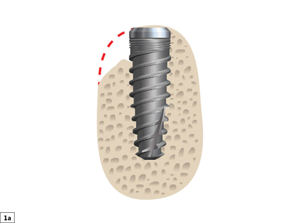
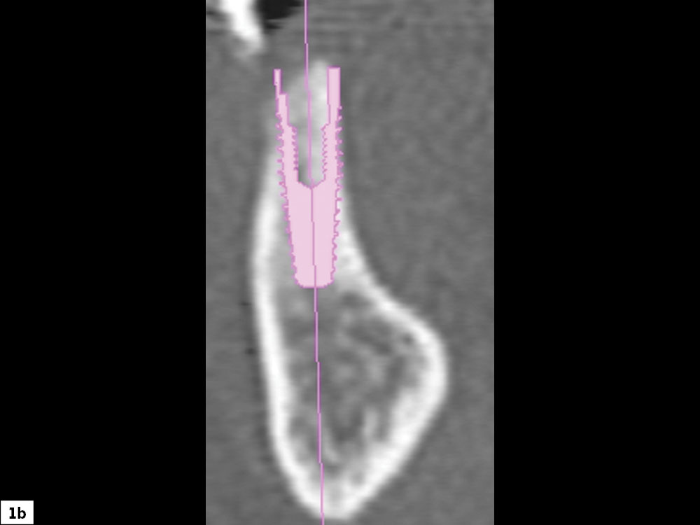
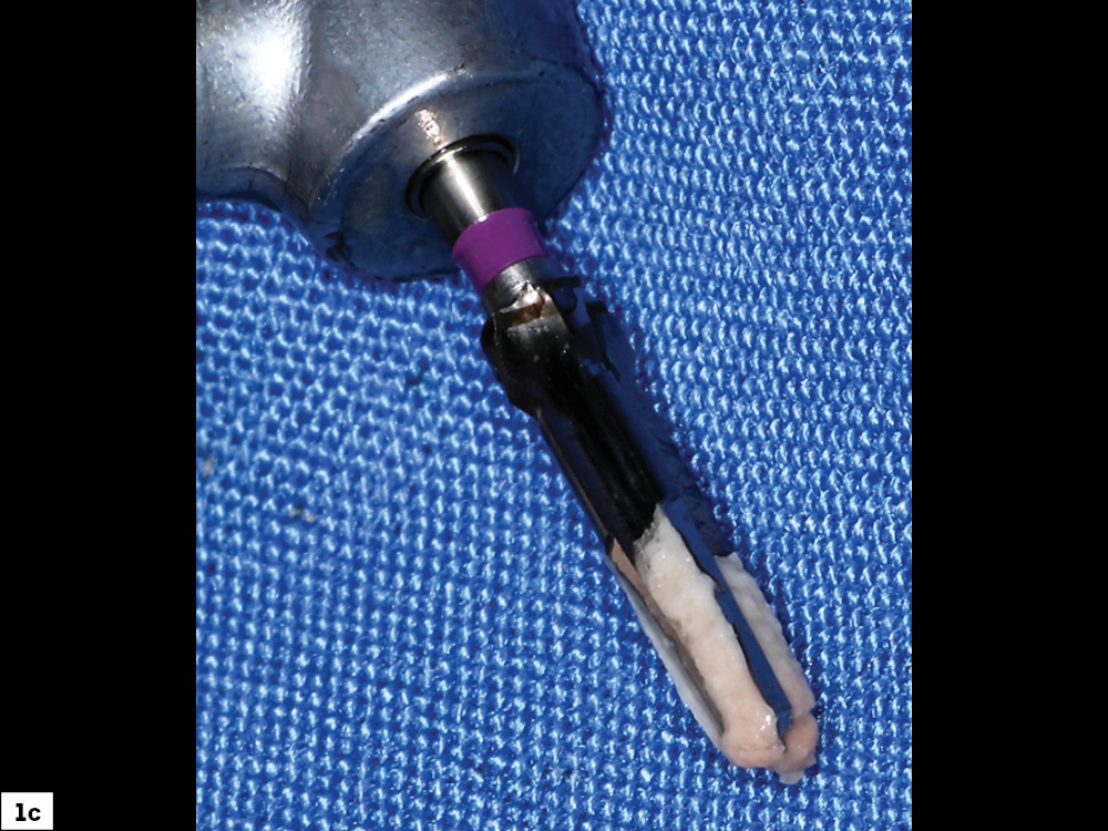
Figures 1a–1c: Small depression defect: Compromised bony ridge width requiring grafting at time of implant placement (1a, 1b). The ideal source of autogenous bone is from the flutes of the surgical bur (1c).
b. Concavity Defect
A concavity-type defect is a horizontal deficiency greater than 2 mm. These bony defects have surrounding bone that may be utilized for graft support and containment of graft material. This is advantageous for space maintenance, which allows for more predictable graft healing. These depression-type bony defects are ideal for clinicians early in their learning curve for ridge augmentation procedures, as they are highly predictable (Figs. 2a, 2b). Depending on the size and location of the deficiency, tenting screws may be required for space maintenance principles.
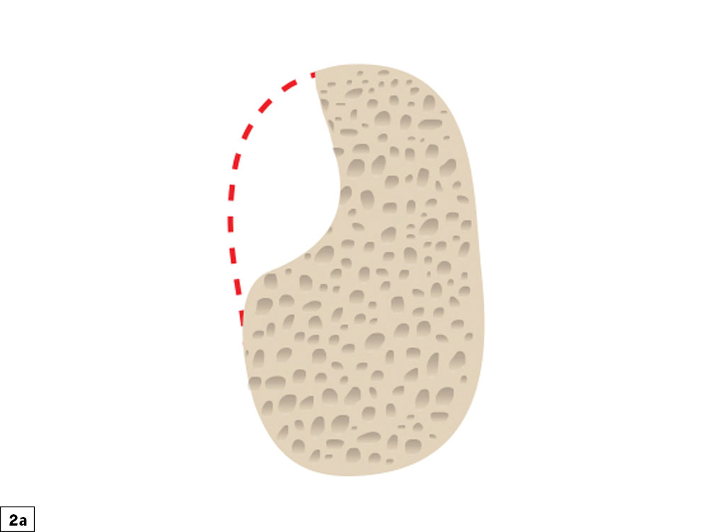
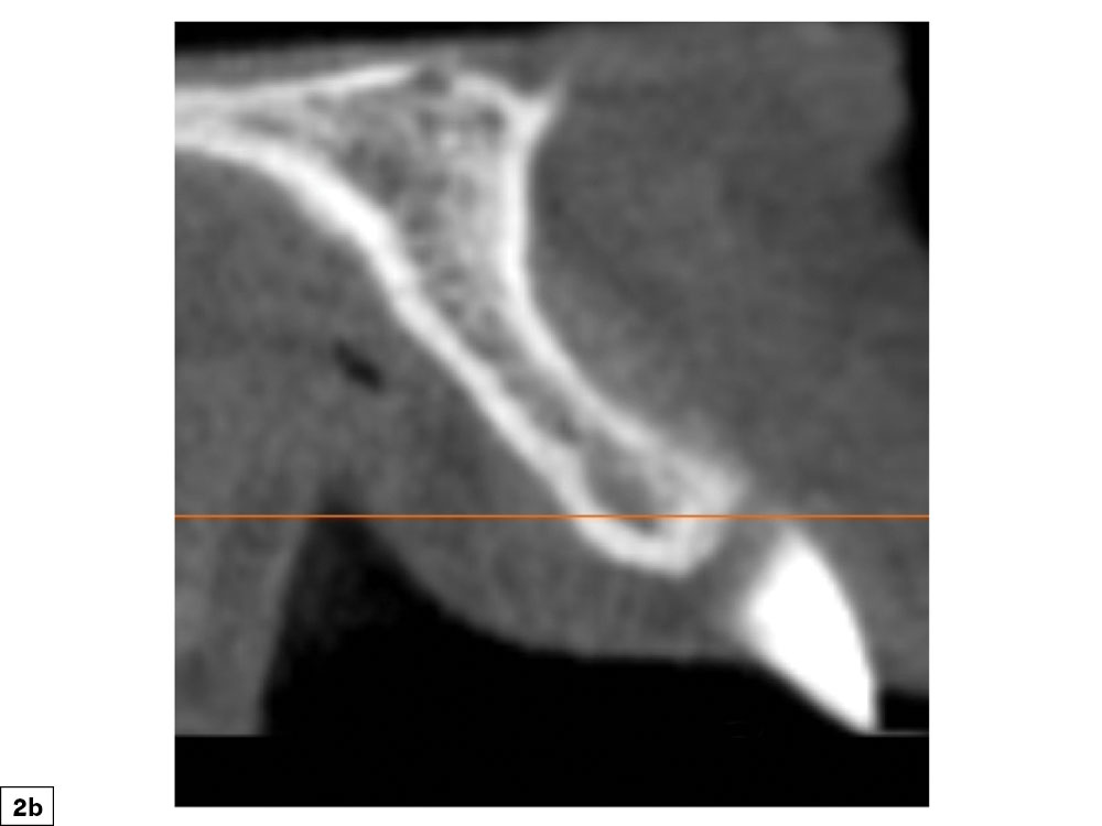
Figures 2a, 2b: Concavity bony defect: Concave defect, which allows for predictable bone grafting procedures.
c. Convex/Straight Bone Deficiency
Deficiencies that are straight/convex are very prevalent, most commonly occurring after loss of the buccal plate or after an extended edentulous time period. Because the defect occurs on an inclined plane, the concept of maintaining space to allow for undisturbed bone growth is challenging. Multiple, stable tenting screws are necessary to prevent micromovement, which is paramount for predictable bone growth. In addition, soft-tissue closure is more challenging, as special emphasis must be used to reduce tissue flap tension to obtain primary closure of the surgical site. Care should be exercised to minimize any pressure on the graft site from the provisional or interim prosthesis (Figs. 3a, 3b).
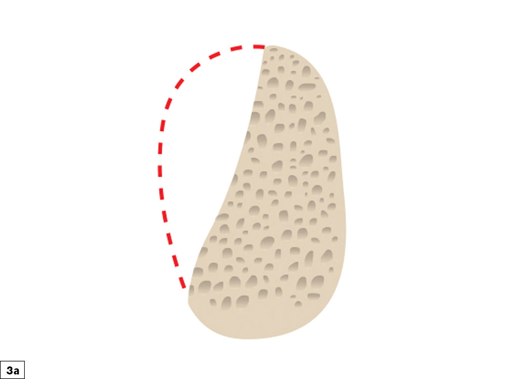
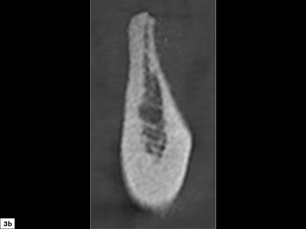
Figures 3a, 3b: Straight/convex bony defect: Width-compromised bony ridges are challenging graft sites due to the difficulty in preventing micromovement of the graft material and space maintenance.
d. Vertical (Height) Defects
Bony defects that require vertical height correction are highly complex and should be reserved for clinicians with advanced experience and skills in complex manipulation of hard and soft tissue. Vertical defects are most commonly the result of the loss of both cortical plates and will necessitate space maintenance in three dimensions. As the vertical defect height is increased, the crown-implant ratio becomes problematic with respect to esthetics and biomechanical factors. The limiting factor of these defects is the interproximal bone level of the adjacent teeth. Clinicians must understand that it is not possible to increase the bone level above the bone height of the adjacent teeth (Figs. 4a, 4b). Unpredictable results occur if there is any compromise in maintaining space, preventing micromovement of the graft material, or achieving tension-free soft-tissue closure.
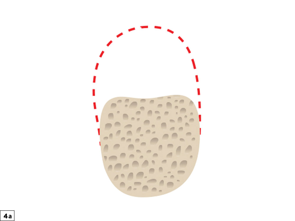
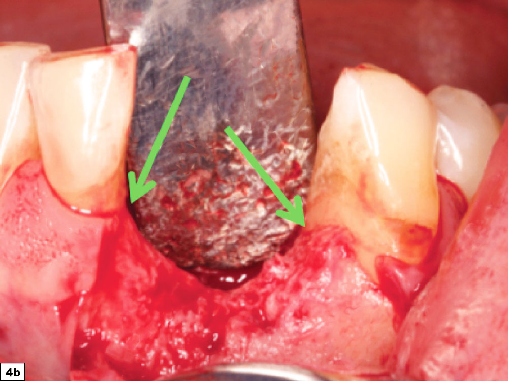
Figures 4a, 4b: Vertical height bone defects: Height-deficient ridges are the most difficult and least predictable to treat, as there are many limiting factors in the consideration of the graft.
e. Buccal-Lingual Defects
Buccal-lingual bony defects, which often occur in the anterior maxilla or anterior mandible, are extremely challenging. These anatomic areas present technical challenges with respect to tissue release, space maintenance and graft containment. However, the most common difficulty with these types of defects is placement of tenting screws, as available bone is often insufficient to obtain fixation of these important holders of the graft space. These types of defects should also be limited to clinicians with extensive surgical and bone grafting experience (Figs. 5a, 5b).
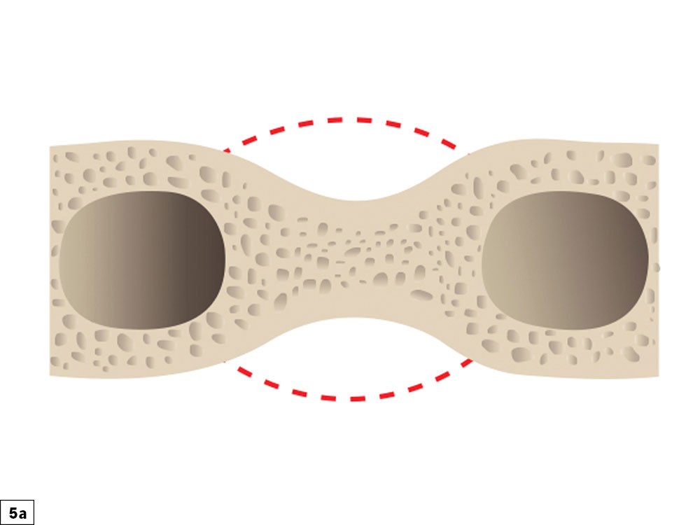
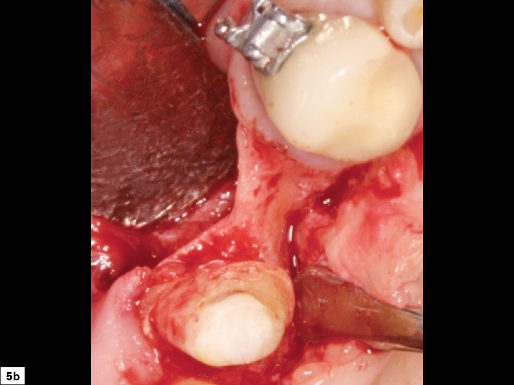
Figures 5a, 5b: Buccal-lingual bony defect: An hourglass type of ridge morphology is more complex, as grafting is indicated on the buccal and lingual aspects, and space maintenance and prevention of micromovement of the graft material are difficult.
STEP 2: FLAP DESIGN AND INCISION
The flap design and incision are crucial steps in obtaining a predictable regenerative result. Ideally, complete access to the surgical site without compromising the integrity of the surrounding tissue should be obtained. As the incision location is planned, the anatomy of the adjacent papillae must be considered to minimize any compromise to the esthetics and function of the tissue postoperatively. The patient’s gingival biotype (thick vs. thin) and the amount of keratinized tissue are always evaluated. Failure to properly plan the incision and flap design during grafting may lead to complications, most commonly incision line opening, resulting in increased morbidity.
The coronal incision is usually positioned on the crest of the ridge, with a more palatal position if the amount of existing attached tissue is compromised. Vertical release incisions are made on the buccal surface and extend to the mucogingival junction. Broad-based incisions are important to prevent interruptions in the vascular supply to the flap and to allow for elevation, retraction, repositioning and suturing without tension. It is imperative that a continuous full-thickness incision be made on bone through the tissue and the periosteum. Incisions that are irregular may lead to maceration of the flap, which compromises the primary blood supply source (periosteal tissue layer). When incisions involve adjacent teeth, papillae-sparing incisions should be completed, leaving a minimum of 1 mm of the papilla intact (Figs. 6a, 6b).
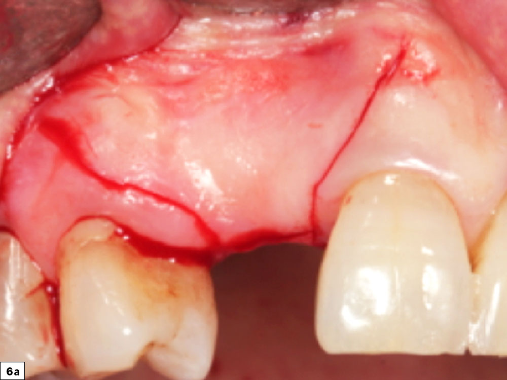
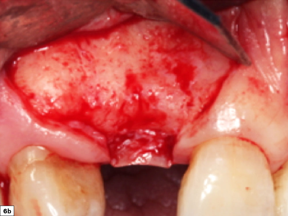
Figures 6a, 6b: Papillae-sparing incision depicting a broad-based design that maintains blood supply and prevents postoperative tissue recession.
STEP 3: REFLECTION AND RELEASE OF THE TISSUE
Tissue Reflection
When exposing the recipient site, nontraumatic elevation of the tissue is required to obtain a full-thickness mucoperiosteal flap. This should include an uninterrupted release of the flap that includes the surface mucosa, submucosa and periosteum. As the tissue is reflected, the underlying bone should be scraped with a bone curette to remove any tissue. Ideally, a specialized periosteal elevator (e.g., 2/4 Molt Curette, Newport Surgical™ Implant and Bone Grafting Instrumentation Kit [Glidewell; Irvine, Calif.]) should be used with the curette edge resting on the bone to prevent tearing of the tissue flap (Fig. 7).
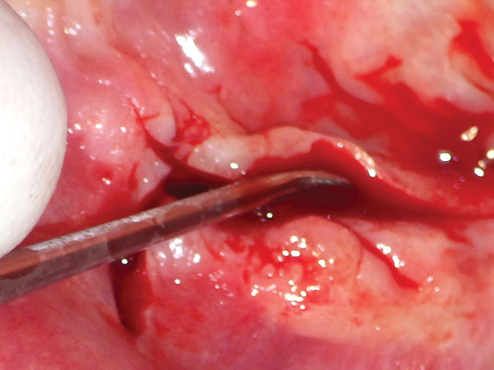
Figure 7: Tissue reflection: Use of a 2/4 molt curette, which allows for nontraumatic soft-tissue exposure.
Releasing Tissue Tension
It is imperative that the flap has complete release of tension to prevent incision line opening. Excessive flap tension will compromise the blood supply to the tissue, which may lead to necrosis and eventual separation of the two edges of the flap closure, resulting in an incision line opening. When this occurs, soft-tissue ingrowth, bacterial contamination, and migration of graft particles may lead to compromised regenerative results.
Flap tension is reduced by releasing the periosteal layer, allowing the elastic fibers of the underlying flap to stretch as the flap is drawn over the graft site. Stretching the tissue may be completed by either periosteal release incisions (shallow incisions with a scalpel blade in the periosteum) or a blunt dissection (Metzenbaum scissors placed into the periosteal tissue layer and opened, resulting in stretching of the tissue fibers). Ideally, extension of the flap should extend at least 5 mm beyond the edge of the adjacent margin after the flap is released (Figs. 8a, 8b).
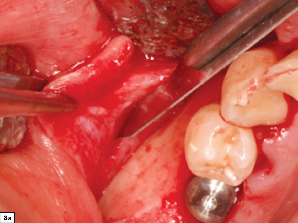
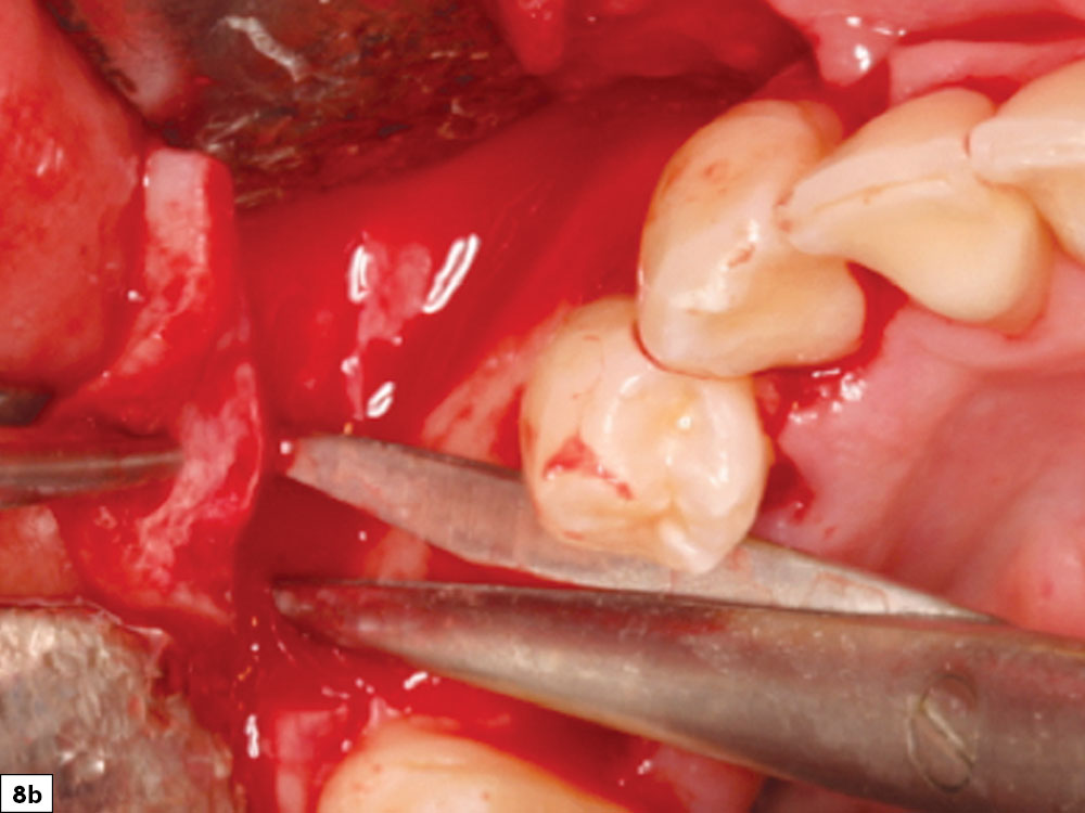
Figures 8a, 8b: Periosteal release incisions with a No. 15 blade (8a), and broadbased tissue release with Metzenbaum scissors (8b).
STEP 4: PREPARATION OF THE RECIPIENT SITE
Soft-Tissue Removal
For predictable bone regeneration to occur, all soft-tissue remnants must be removed from the bony recipient site. Soft-tissue fibers remaining on the host recipient bone will compromise the attachment of the newly regenerated bone to the underlying basal layer. Tenacious tissue may be removed with a sharp bone curette or a coarse acrylic bur (Fig. 9).
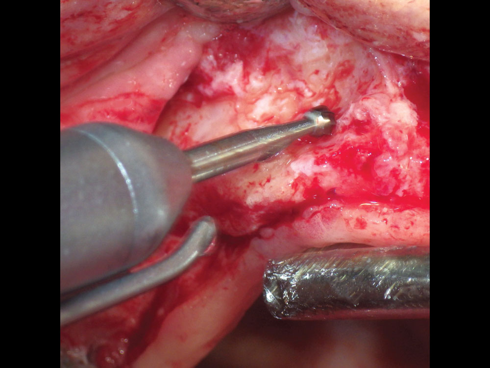
Figure 9: Soft-tissue removal with No. 8 round carbide bur.
Decortication
The decortication of the recipient site includes creating pilot holes into the cortical bone, which initiates the regional acceleratory phenomenon (RAP). RAP is the cellular process that stimulates and accelerates the healing rate of a graft site.5 Placing pilot holes into the cortical bone acts as a “noxious stimulus,” and the healing rate of a decorticated graft site has been shown to increase 2–10 times the normal healing rate.6 The holes create an open pathway to the underlying trabecular bone, where blood flow into the graft site will increase revascularization (angiogenesis) and allow for bone growth factors to readily enter the graft site. This acceleration is accomplished by the introduction of platelets to the area, which degranulate and release growth factors, including platelet-derived growth factor (PDGF) and transforming growth factor (TGF). The decortication process may be accomplished with the use of cross-cut fissure burs or small round burs that are used to perforate the cortical plate. Copious amounts of chilled saline should be used to prevent thermal trauma (Fig. 10).
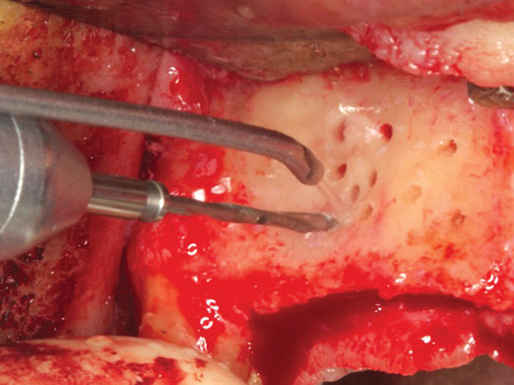
Figure 10: Decortication holes with a cross-cut fissure bur leading to the initiation of the RAP, allowing for faster and more predictable healing.
STEP 5: SPACE MAINTENANCE
The concept of space maintenance to support the graft area is the key to success of the GBR process. The creation and continued structural support of the graft space is most commonly accomplished with membranes supported by tenting screws. If space maintenance is compromised in any way (i.e., loss of structural integrity or movement), then bone regeneration will be less predictable.
Tenting Screw Concept
The use of specialized tenting screws has made the GBR process more predictable as the membrane is easily supported, thereby preventing collapse of the graft site. The design of tenting screws allows for the larger head of the screw to maintain vertical and horizontal support. This support system allows for the creation of a predictable and controlled final contour of the graft and the bone regeneration process to proceed in an unaltered manner. Bone fixation screws on the market today are most commonly non-resorbable titanium screws with aggressive thread designs, a wide head, and smooth neck contours for atraumatic tissue support. If the head of the screw perforates through the membrane, the vertical support will be decreased, and the particulate graft is subject to pressure and micromovement. When support is lost, the final volume and consistency of the matured ridge will be compromised.
Number of Tenting Screws
The amount of support required to maintain the spatial dimensions of the graft site determines the number and positioning of the screws. Usually, multiple screws are anchored in the recipient site to form a dome over the graft site that replicates the dimensions of bone needed for ideal implant placement. Ultimately the tenting screws act as “tent poles” to support the membrane, decrease graft mobility, and relieve external pressure on the graft.7
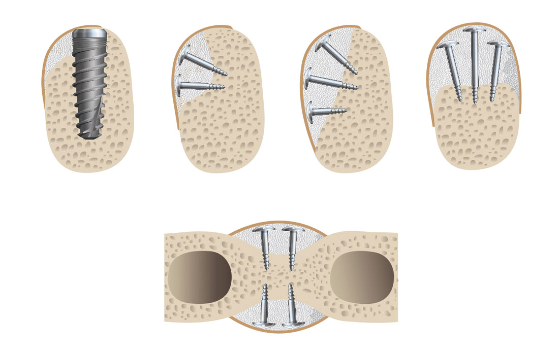
Positioning of Tenting Screws
The positioning of the screws should be planned in a manner that will result in a dome shape that is formed by the heads of the screws, which should match the intended contour of the final ridge form. The use of multiple screws in this technique creates very specific ridge forms that cannot be attained with unsupported membranes. Usually, screws are placed in a nonparallel fashion approximately 3–4 mm apart, which allows sufficient space for angiogenesis to occur. The location and trajectory of adjacent tooth roots must be determined to prevent screw placement near a tooth root. Ideally, intraoperative radiographs should be taken to verify ideal positioning in relation to tooth root position (Figs. 11a, 11b).
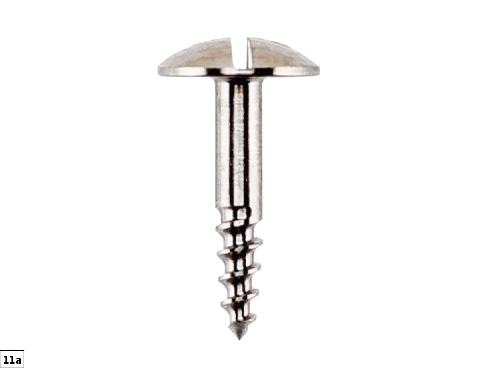
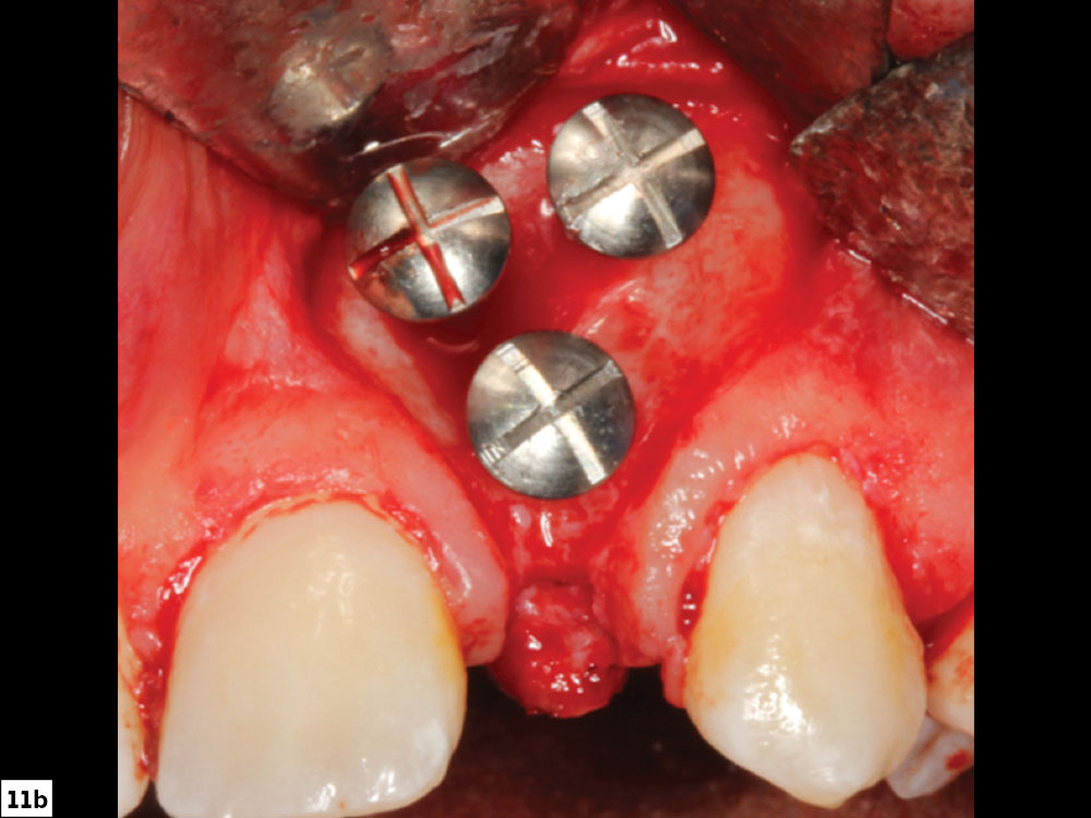
Figures 11a, 11b: Large-head tenting screw (11a); tenting screw positioning (11b).
STEP 6: PLACEMENT OF THE BONE GRAFT
When placing graft material into a bony defect, a systematic layered approach should be utilized, depending on the size and location of the graft site.
Layer 1: Autograft
The first layer of the GBR graft is composed of autogenous bone. Autogenous bone is usually indicated in any bony defect that requires horizontal bone growth of greater than 3 mm or in all cases of vertical regeneration. In smaller defects of less than 3 mm, autogenous bone is optional. Autogenous bone is typically harvested from any accessible region of cortical/cancellous bone present in the oral cavity (tuberosity, ramus or symphysis). The small autograft particulate pieces are placed directly on the host bone surrounding the bone screws. Graft particles are transferred from the surgical bowl to the graft site and placed underneath the tenting screw heads with cotton forceps or a molt curette.
Layer 2: Allograft
Allogenic bone is the most ideal bone substitute used today for GBR techniques. Allografts are available in many different preparations, with the most common being freeze dried bone allograft (FDBA) and demineralized FDBA (DFDBA). The recommended graft material (e.g., Newport Biologics™ Mineralized Cortico/Cancellous Allograft Blend [Glidewell]) should be hydrated with sterile saline (0.9% sodium chloride) or platelet-rich fibrin (PRF) and then gently condensed into the recipient site. Small increments of material should be added into the site, and a bone-packing instrument, such as the Bone Carrier and Spoon included with the 12-piece Newport Surgical Implant and Bone Grafting Instrumentation Kit (Glidewell), should be utilized to condense the material to avoid air spaces (Figs. 12a, 12b).
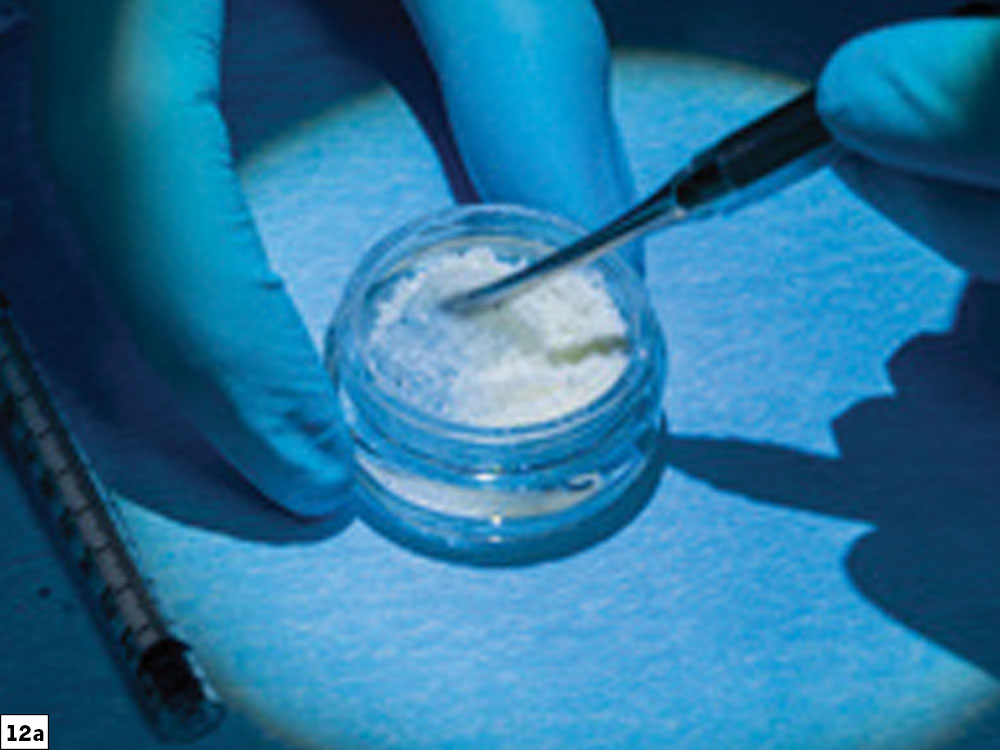
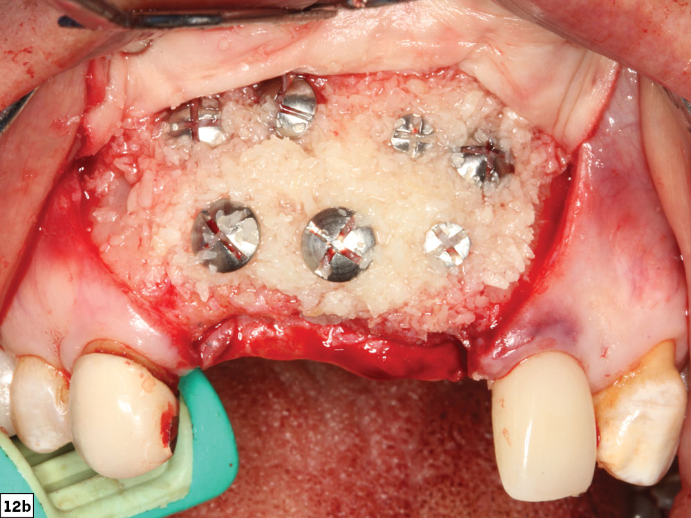
Figures 12a, 12b: Newport Biologics Mineralized Cortico/Cancellous Allograft Blend (12a); graft material added to recipient site (12b).
STEP 7: SELECT AND PLACE THE BARRIER MEMBRANE
Barrier membranes are generally used in guided bone regeneration procedures to act as a biological and mechanical barrier against the invasion of fibrous tissue into the developing graft site. Most membranes will allow for the migration of the slower-migrating bone-forming cells into the defect sites. During the bone regeneration process, there is a competition between soft-tissue and bone-forming cells to invade the surgical site. In general, soft-tissue cells migrate at a much faster rate than bone-forming cells. Therefore, the primary goal of barrier membranes is to allow for selective cell repopulation and to guide the proliferation of various bone-forming cells during the healing process. This will allow for angiogenesis and the migration of osteogenic cells that replace the blood clot with woven bone, which eventually transforms into load-bearing lamellar bone. If a barrier membrane is not utilized, lack of isolated space maintenance will result in soft-tissue integration and compromised bone growth.
Types of Membranes
Barrier membranes in GBR procedures are usually classified as either resorbable or non-resorbable. Resorbable membranes (e.g., collagen) are the most commonly used membranes for GBR techniques. Resorbable membranes are cost-effective, easy to use and naturally biodegradable, and have varying resorption rates. For ridge augmentation procedures, a longer-acting collagen barrier such as the Newport Biologics Resorbable Collagen Membrane 4–6 (Glidewell) is recommended. These cross-linked membranes are ideal for containing the graft, especially for grafts that require longer healing periods (Figs. 13a–13c).
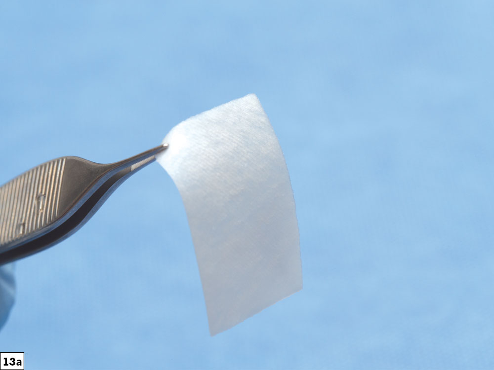
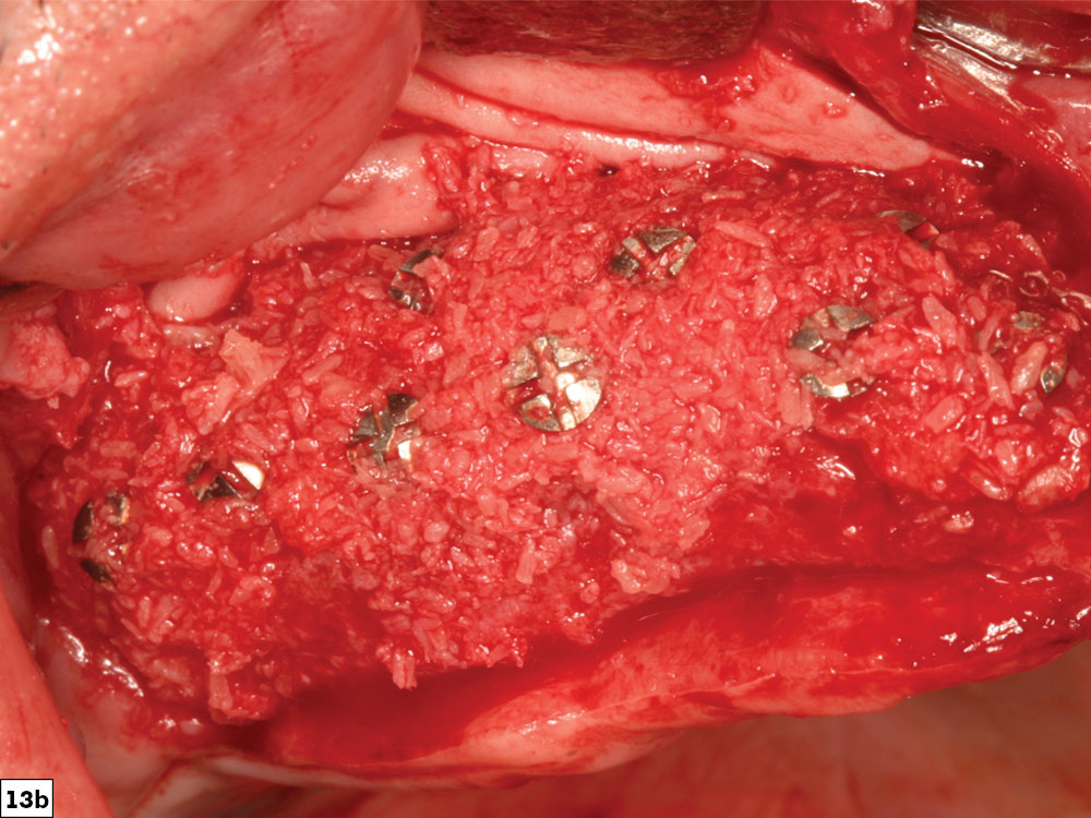
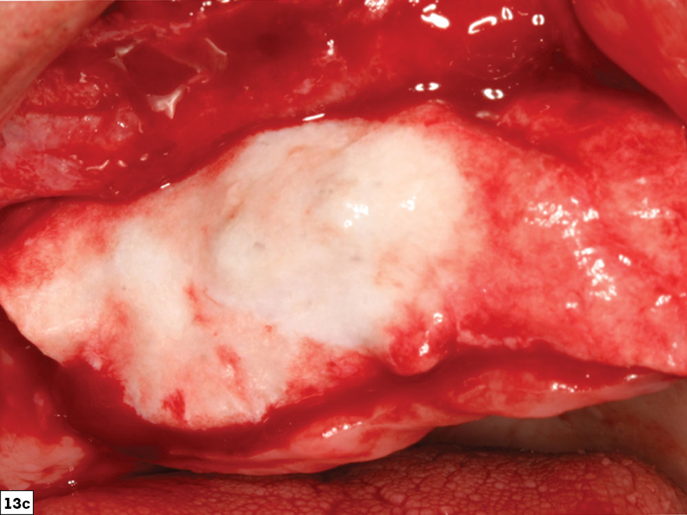
Figures 13a–13c: Newport Biologics Resorbable Collagen Membrane 4–6 (13a); maxillary anterior graft site (13b); collagen membrane positioned over graft site (13c).
In contrast, non-resorbable membranes are bio-inert materials, which are less advantageous because they require a second surgical procedure for removal. Dense polytetrafluoroethylene (d-PTFE) membranes are the most commonly used material with or without titanium reinforcement (e.g., CytoSurg™ Non Resorbable PTFE Membrane [Salvin Dental Specialties; Charlotte, N.C.]). Although they exhibit excellent biocompatibility, superior mechanical strength and increased rigidity, and generally achieve more favorable space maintenance than unsupported resorbable membranes, they are associated with increased incision line opening and increased complications.
Sizing and Positioning of Membranes
The size of the membrane must be large enough to completely cover and extend approximately 2–3 mm beyond the graft site. The barrier membrane may be fixated prior to the placement of graft material with bone tacks. The initial fixation may be completed either apically or on the lingual aspect of the ridge. Fixation of the membrane before placing the particulate graft ensures that the membrane will not move after the graft material is added.
Final Positioning and Stabilization of the Membrane
After the graft material, in one or two layers, is positioned, the membrane is stretched over the graft site. The membrane should be of sufficient size to totally encompass the entire graft. The goal of the membrane fixation is to prevent any movement, which could negatively affect the wound healing. In most cases, the final fixation is on the palatal aspect of the ridge with two tacks. Additional fixation can be used as needed in large graft sites to limit membrane movement. Alternatively, in some cases, the edges of the membrane may be tucked beneath the flap margins at the time of closure to provide stabilization without bone tacks (Fig. 14).
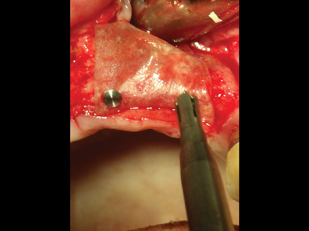
Figure 14: Newport Biologics Resorbable Collagen Membrane fixated with bone tacks. In some cases, the membrane can be fixated on one side apically or lingually prior to bone graft placement.
Bone Growth Factors
Bone growth factors may be used in combination with barrier membranes to enhance the formation and mineralization of bone, especially in larger cases. In addition, bone growth factors may induce undifferentiated mesenchymal cells to differentiate into bone cells that trigger a cascade of intracellular reactions for the release of additional bone growth and cell-enhancing factors. The two most common bone growth factor techniques utilize blood concentrates (platelet-rich fibrin) and recombinant human bone morphogenetic protein-2. Multiple clinical studies have shown increased soft-tissue healing, enhanced healing of grafted bone, promotion of angiogenesis, and faster wound healing with the use of bone growth factors (Fig. 15).8
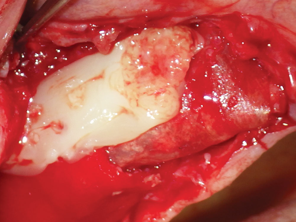
Figure 15: Platelet-rich fibrin (PRF) growth factor placed over the barrier membrane. PRF can also be mixed with the bone graft material for increased bone healing results. See more details about PRF procedures in Dr. Resnik’s article, “Enhancing Bone Regeneration with the Use of Platelet Concentrates” (Chairside® Vol. 15, Issue 1).
STEP 8: ENSURE PROPER CLOSURE
The final closure of the bone graft site is a crucial step in the bone grafting procedure. Most importantly, a tension-free flap adaptation is the key to predictable and consistent results. If incision line opening occurs, the morbidity of the procedure will increase. Therefore, meticulous principles should be adhered to with respect to a tension-free flap design, ideal suture technique, and close postoperative evaluation of the surgical site. The suture selected should be made from a material that has high tensile strength, ideally polyglycolic acid (PGA) (absorbable), such as the REDISORB® PRO (Glidewell), or PTFE (nonabsorbable). Specific attention must be directed to proper approximation of the margins of the flap to confirm there is no overlapping of the tissue flaps or bone graft material present within the margins.
Most commonly, horizontal mattress and interrupted sutures are used to close the graft site. One of the primary advantages of using the horizontal mattress sutures is the ability to “evert” the tissue margins. By everting the margins of the flap outward, the connective tissue layers will be approximated against each other. Additional interrupted sutures may be used to approximate all edges of the wound. The vertical incisions may be closed with 4-0 chromic, such as the REDIGUT® Chromic Pro 4-0 (Glidewell), as they may greatly reduce the post-op formation of tissue scars.
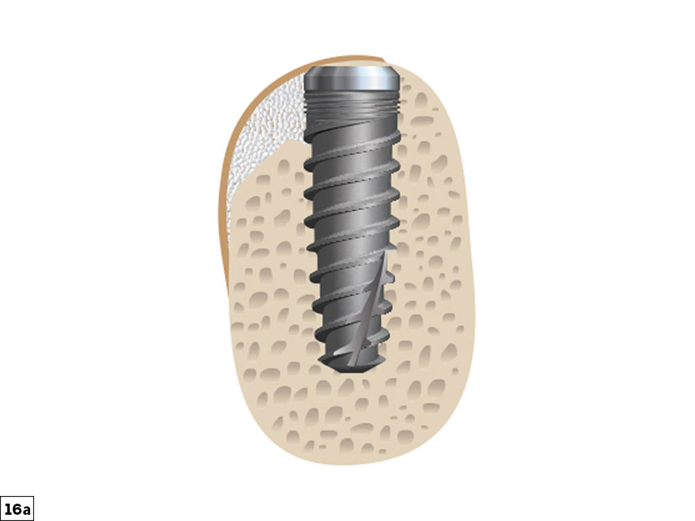
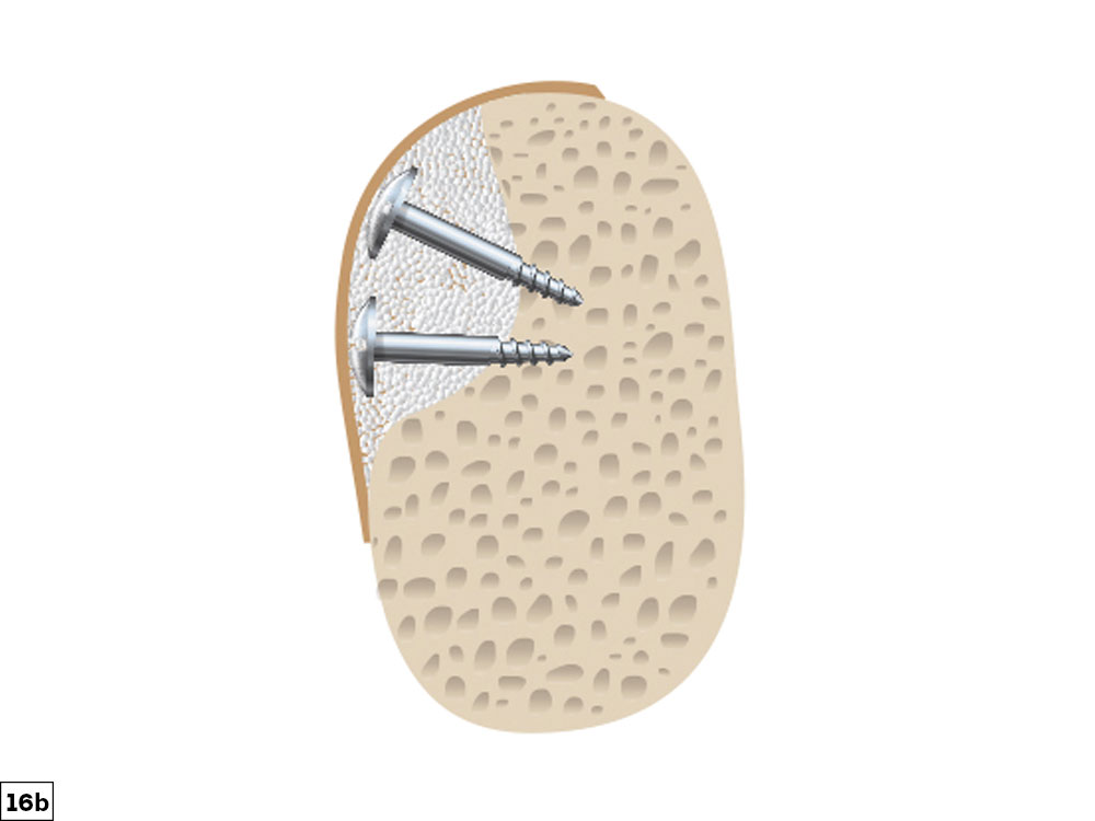
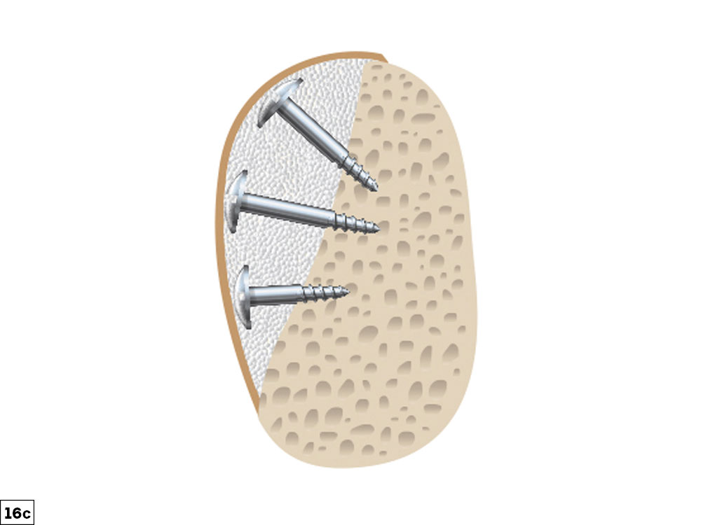
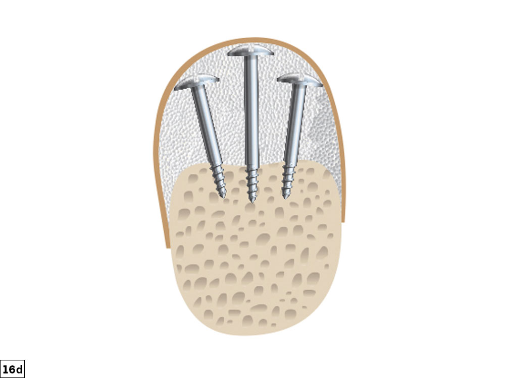
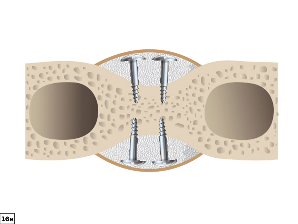
Figures 16a–16e: Examples of completed ridge augmentation for the five bone defect types discussed: small depression (16a), concavity (16b), straight/convex (16c), vertical (16d), and buccal-lingual (16e).
CONCLUSION
To obtain optimal function and esthetics in implant dentistry, the hard and soft tissues need to be present in adequate volume and quality. The guided bone regeneration technique has been shown to be very successful and predictable in augmenting these tissues. The correction of alveolar bony ridge deficiencies, once thought to be difficult or impossible, should be in every clinician’s procedural arsenal (Figs. 16a–16e). However, these procedures are technique-sensitive, and therefore all procedural steps must be strictly followed. In this article, a GBR ridge augmentation protocol has been discussed in eight procedural steps that allow for predictable bone grafting (Figs. 17a–19b).
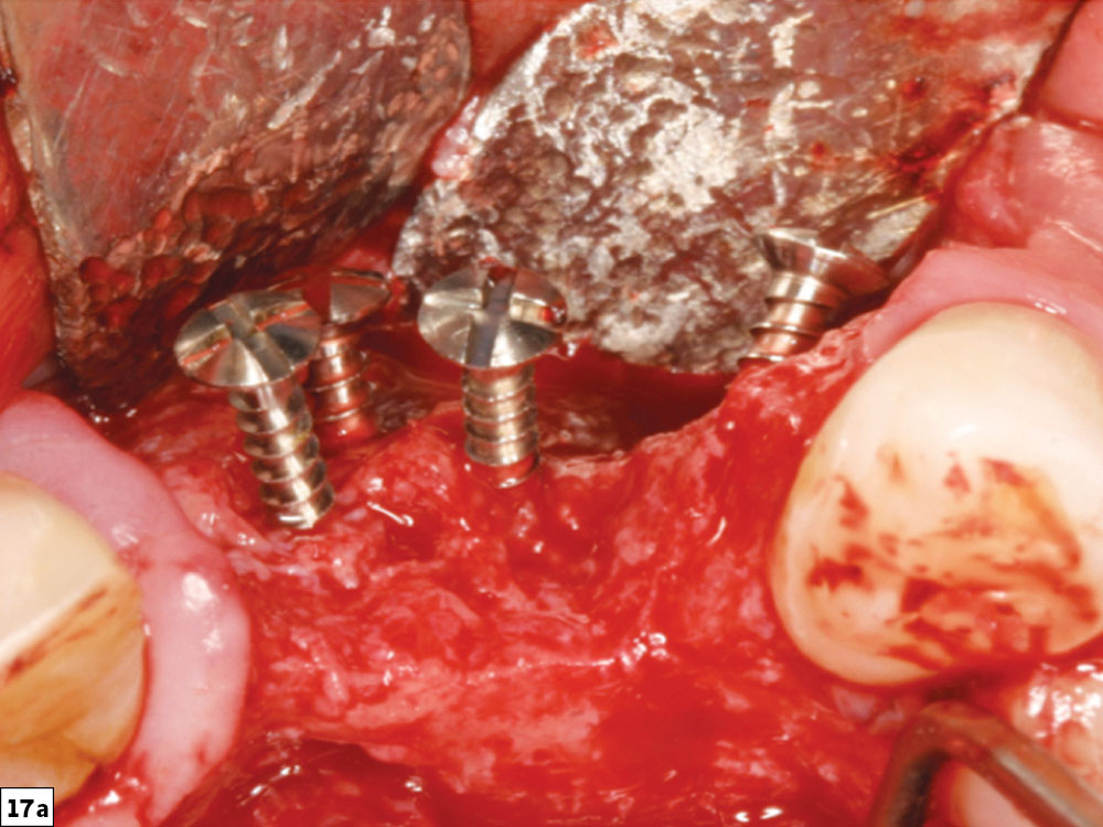
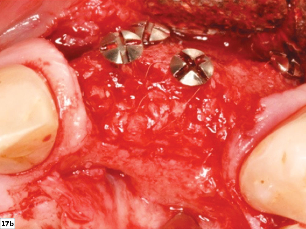
Figures 17a, 17b: Concavity-type defect (17a) and final post-healing image depicting bone growth to the level of the tenting screws (17b).
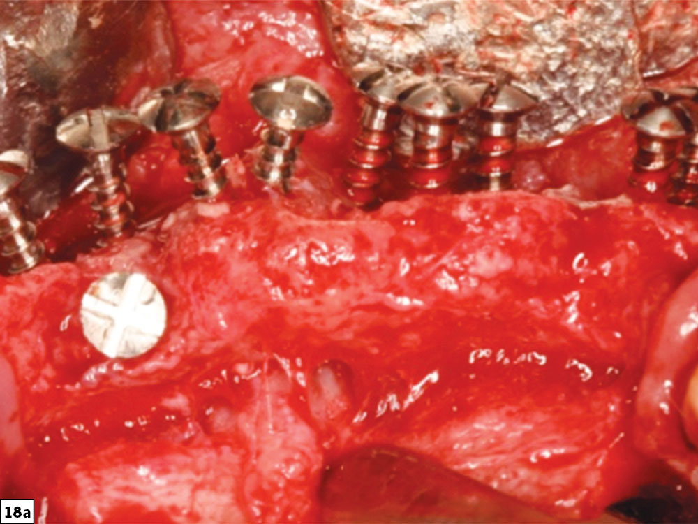
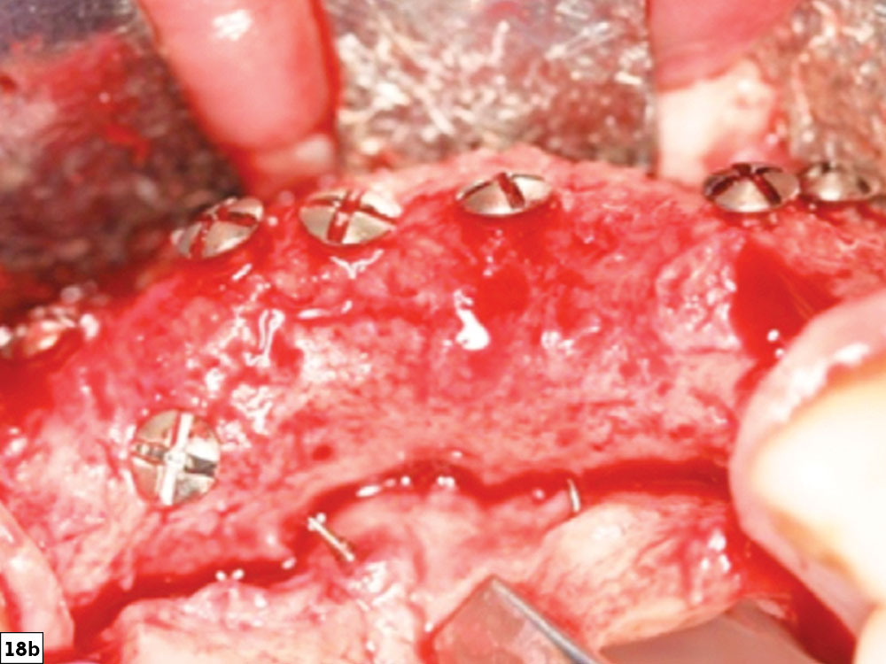
Figures 18a, 18b: Straight/convex-type bone defect (18a), and final post-healing image revealing bone growth in height and width ideal for future implant placement (18b).
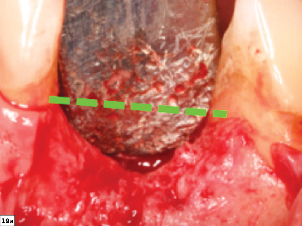
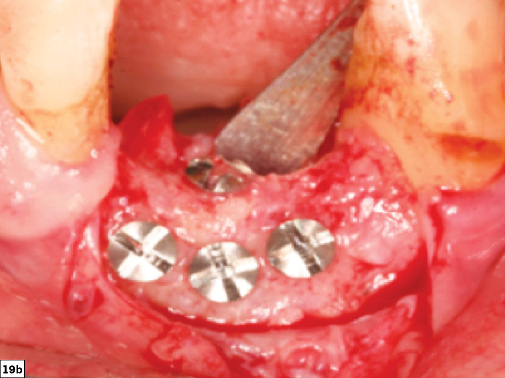
Figures 19a, 19b: Very challenging vertical defect (19a) and final post-healing image depicting horizontal and vertical bone growth to the level of the adjacent teeth (19b).
Available CE Course
References
- ^Dahlin C, Linde A, Gottlow J, Nyman S. Healing of bone defects by guided tissue regeneration. Plast Reconstr Surg. 1988 May;81(5):672-6.
- ^Retzepi M, Donos N. Guided bone regeneration: biological principle and therapeutic applications. Clin Oral Implants Res. 2010 Jun; 21(6):567-76.
- ^Bornstein MM, Halbritter S, Harnisch H, Weber HP, Buser D. A retrospective analysis of patients referred for implant placement to a specialty clinic: indications, surgical procedures, and early failures. Int J Oral Maxillofac Implants. 2008 Nov-Dec;23(6):1109-16.
- ^Resnik R. Misch’s Contemporary implant dentistry. 4th ed. St. Louis: Mosby; 2020.
- ^Frost HM. The regional acceleratory phenomenon: a review. Henry Ford Hosp Med J. 1983;31(1):3-9.
- ^Melcher AH, Accursi GE. Osteogenic capacity of periosteal and osteoperiosteal flaps elevated from the parietal bone of the rat. Arch Oral Biol. 1971 Jun;16(6):573-80.
- ^Caldwell GR, Mealey BL. A prospective study: alveolar ridge augmentation using tenting screws, acellular dermal matrix and combination particulate grafts. A thesis for Master of Science in Periodontics — University of Texas Health Science Center at San Antonio Graduate School of Biomedical Sciences. May 2013.
- ^Laney WR. Glossary of oral and maxillofacial implants. Berlin: Quintessence Publishing Co Ltd; 2007. 212 p.
REDISORB and REDIGUT are registered trademarks of Myco Medical Supplies, Inc.